Buildings consist of architectural, structural, and MEP services. It is not easy to construct a building with detail and accuracy with normal construction drawings. They don’t provide the required information for contractors, subcontractors, fabricators, and installers. That is why construction shop drawings are important.
Table of Contents
Toggle
What is Shop Drawing?
Types of Shop Drawings
- Architectural shop drawings: These types of shop drawings provide details about the pre-fabrication and installation of architectural elements of a building like walls, doors, windows, etc.
- Structural shop drawings: Dimensions, tolerances, and welding details are just some of the many things that are shown on these drawings, which are used in the fabrication and assembly of structural steel parts.
- MEP shop drawings: Mechanical/HVAC, electrical, plumbing, and fire protection services are difficult to fabricate and install, and their coordination is also a difficult task. MEP shop drawings provide detailed drawings of MEP services after clash detection and coordination.

- Façade shop drawings: Façade is an important feature of a building that decides its aesthetics and thermal comfort. These shop drawings give a detailed depiction of façade components and their assembly.
- Assembly drawings: These diagrams show how different parts go together and how they should be attached, as well as where they should be located.
- Millwork shop drawings: Cabinetry, millwork, and other decorative additions to a building can be made according to the specifications laid out in millwork drawings.

Role of Construction Shop Drawings in the Building Process
The shop drawings for a project are the technical documents that are required to convey how the fabricator and their team will create, assemble, and install the components of the project that have been requested by the designer.
They provide the fuel for a unified vision, which has proven to be a crucial component in pulling together difficult building projects.
Key Elements of a Construction Shop Drawing
- Arrange views
Numerous views depicting the component from various angles compose the whole of a shop drawing. All of the views should work together to give contractors, builders, and fabricators a comprehensive description of the features and their positions.
Axonometric Views | Orthographic Projection | Sectional Views | Assembly Drawings |
Different Axonometric views, such as the Isometric, Dimetric, and Trimetric, show the fabricator the entirety of a part at once and highlight its most important aspects. | The front, left, right, top, and bottom views, each rotated by 90 degrees from the other, are the most helpful in explaining most building components. | They provide detailed cross-sectional information about a specific component or assembly, allowing for a clearer understanding of its internal structure, dimensions, and relationships with surrounding elements. | Fabricators can more easily figure out how to manufacture various elements of a system if they can see how those parts go together. |
|
|
|
|
- Information required to fabricate the product
The shop drawing should include all necessary dimensions, manufacturing standards, and any unique instructions for fabrication. Fabrication workers should be able to tell from the submittals and shop drawings exactly what needs to be made.
Fabricators often only use the shop drawing, not the construction documentation, for guidance during the manufacturing process.
- Indication of dimensions requiring worksite verification
Most worksite dimensions, such as those between surfaces, must be confirmed. Depending on job site conditions, a construction drawing’s dimension may change from extremely small to enormous increments.
It is crucial that the produced item arrives on site ready to install. The contractor must carefully measure and verify dimensions. Many fabricated elements like structural steel and precast concrete can be ordered from plan dimensions in new construction.
Field dimensions must be checked before manufacturing in remodeling and renovation. Some fabricators, like cabinet and casework suppliers, prefer to verify the dimensions themselves rather than rely on the contractor.
- Placement or installation information
Fabricators and manufacturers can incorporate symbols, information, or installation guidelines. Major building systems might need to be reviewed by an external party.
For instance, the mechanical contractor may supply a commercial chiller, but the client must arrange for wiring, plumbing, rigging, insulation, and commissioning. The installation information must be reviewed by several third parties to ensure they are supplying suitable equipment and the correct arrangement of services.
- Revision history
As shop drawings undergo revisions during the design and construction process, it is essential to maintain a revision history, documenting the changes made, the revision number, and the date of each revision.
- Schedules
Schedules provide a tabular representation of various components or materials, including their quantities, specifications, and locations. Examples include door schedules, window schedules, or finish schedules.
- Material specifications
Contractor shop drawings specify the materials to be used for each component. This may include information on the type, grade, size, finish, and other relevant properties of the materials.
- Indicate dimensions clearly
When information is presented clearly, it is processed fast and correctly. To save time and effort during fabrication, it is important to clearly indicate the scale and position of features.
Distances should be shown using parallel double-headed arrows. To reduce confusion, display dimensions outside the drawing view and use extension lines to specify which feature is being referred to.
- Applying Tolerances
No matter how precise a fabrication process is, it will always fall short of producing an exact value for a given dimension. This variation in value is known as the dimension’s tolerance.
Every machine makes mistakes, and it is often more efficient to compromise accuracy for speed. No drawing is complete without an indication of the range of values you are willing to accept for each component dimension.
Step-By-Step Process to Create Construction Shop Drawings.
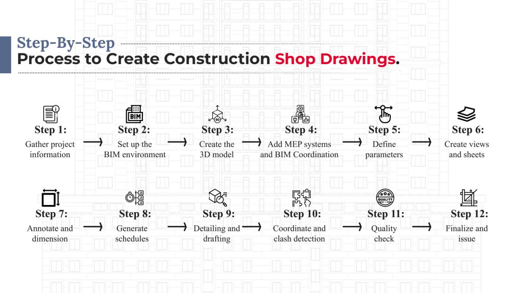
Step 1: Gather project information
Gather all necessary documentation for the project, including architectural plans, structural drawings, MEP (Mechanical, Electrical, and Plumbing) drawings, and other specifications.Step 2: Set up the BIM environment
Begin a new project in the BIM program of your choice including Autodesk Revit or ArchiCAD. Make any project-specific adjustments, such as setting up the units, drawing templates, and other tools you will need.Step 3: Create the 3D model
To get started, use the architectural and structural drawings to make a 3D model of the structure. Construct the model’s framework by setting in place the necessary walls, floors, roofs, columns, beams, etc. Don’t forget to add in things like doors, windows, and staircases.Step 4: Add MEP systems and BIM Coordination
The 3D model needs to incorporate the MEP (mechanical, electrical, and plumbing) systems. MEP components such as ducting, piping, electrical conduits, and fixtures must be installed. Integrate these components with the architectural and structural framework with BIM clash detection and coordination.Step 5: Define parameters
Materials, dimensions, and attributes should all be assigned to model elements. The shop drawings and schedules will incorporate this data.Step 6: Create views and sheets
Create the necessary shop drawing views from the model. Floor plans, sections, elevations, and details are all examples of possible perspectives. Set up the sheet layouts and arrange the views.Step 7: Annotate and dimension
Add labels, measurements, tags, and symbols to the drawings. Dimensional, callout, remark, and other annotations are all part of this process.Step 8: Generate schedules
Create schedules for various components or systems, such as doors, windows, finishes, quantities, and materials. These schedules can be automatically generated from the BIM model and will update as the model changes.Step 9: Detailing and drafting
Begin the process of creating the actual building shop drawings. This involves extracting specific views from the model and adding additional details, annotations, and dimensions specific to construction requirements. Use appropriate drafting standards and conventions.Step 10: Coordinate and clash detection
Conduct a clash detection analysis to determine if there will be any clashes between the various construction systems and components. Find a way to reconcile these differences by modifying the model’s components to eliminate conflict.Step 11: Quality check
Review and quality check the shop drawings for accuracy, completeness, and compliance with project requirements. Make changes as needed per input from the design team and other stakeholders.Step 12: Finalize and issue
Once the shop drawings are reviewed and approved, finalize the drawings and prepare them for distribution. Generate PDF or CAD files as per project requirements and distribute them to the relevant parties, such as contractors, fabricators, and suppliers.Why Are Construction Shop Drawings Important?
Construction shop drawings are undeniably an important part of the AEC industry. Let us take a look at the reasons why they are important:
- Help in smooth and streamlined fabrication and installation of architectural, structural, and MEP components
- Allow us to get a precise design model, optimize the construction schedule, accurately estimate costs and conduct thorough quantity takes, raise the bar on quality in manufacturing, and smooth handover
- Provide stakeholders with easy, detailed, and comprehensive information.
- Shop drawings aid in reducing risks and liabilities by increasing collaboration and coordination
- Improves engineering accuracy and analysis capabilities
- They are an integral part of the permit shop drawing submittal process.
Futuristic Trends in Shop Drawings
- SWAPP: For AI-Powered Architectural Shop Drawings
Intelligent, cutting-edge AI algorithms power SWAPP, which speeds up the production of precise, comprehensive, and detailed architectural shop drawings and as-built drawings.
Explore Our As Built Drawing Services – As-built services refer to documentation and drawings that accurately represent the final state of a construction project.
Using SWAPP, you can save the time-consuming process of manually making countless construction working drawings. Reduced project duration and man-hours are the direct result of automating the shop drawing process.
- Part3: Shop drawing review automation.
It may take several days and a number of individuals to examine shop drawings if it is of a large project or require a great deal of collaboration to achieve a full and complete evaluation. It takes a lot of time and effort to manually coordinate everything.
It is crystal apparent where the document is in review, who is accountable for it at any given time, and which version each person should be looking at thanks to automation using integrated construction management software like Part3.
BIM is the Future of Construction Shop Drawing Creation
The utilization of Building Information Modeling (BIM) for creating shop drawings and construction drawings offers a comprehensive and efficient approach to accurately representing a construction project.
By leveraging the power of BIM software, architects and engineers can create detailed 3D models, coordinate multiple trades, and produce high-quality shop drawings that enhance communication, reduce conflicts, and improve overall project outcomes.
Emphasizing collaboration, accuracy, and continuous improvement, the process outlined in this guide provides a solid foundation for achieving success in construction shop drawing creation with BIM.
Frequently Asked Questions (FAQs):
Errors often arise from outdated design inputs, poor coordination between trades, and insufficient model detail.
BIM extracts coordinated, clash-free drawings directly from 3D models, improving precision and consistency.
MEP contractors, steel fabricators, façade specialists, and interior fit-out teams depend on shop drawings for accuracy.
They remove ambiguity by defining exact dimensions, materials, and assembly details before site execution begins.
Shop drawings translate design intent into fabrication-ready details, ensuring components are manufactured and installed exactly as planned.

Extract quantities for costing and managerial management.
To know more about how we can help you improving your project cost efficacy
Our Services
Latest Post


Get A Free Quote
BIM Construction is the Future
Building information modeling (BIM) is the future of building design and construction. Get in touch with our BIM Experts.